
When designing electronic devices, one of the biggest decisions you’ll face happens before a single component gets placed — choosing between Through-Hole Technology (THT) and Surface Mount Technology (SMT). It’s like deciding between manual and automatic transmission — neither is universally “better,” but each shines in specific situations. Get this choice wrong, and you’re setting yourself up for headaches down the road.
The stakes are surprisingly high here. Pick the wrong assembly method, and you might end up with circuit boards that cost way more than necessary, production delays that wreck your timeline, or worst of all — devices that fail in customers’ hands. This guide cuts through the technical jargon to help you make the right call for your specific needs, whether you’re working on a one-off prototype or planning mass production for your next big product launch.
Key Takeaways
- THT components can take a serious beating — their mechanical strength makes them perfect for devices that face constant vibration or rough handling
- SMT packs an impressive 50–100 components per square inch while THT boards look practically empty in comparison — that’s why modern gadgets keep getting smaller
- Want the best of both worlds? Pin-in-paste soldering lets you mix THT and SMT on the same board without needing two separate production runs
- Those IPC standards aren’t just boring paperwork — they’re your roadmap to boards that actually pass quality testing the first time around
- Be honest about where your device will live — a board for a factory floor needs different assembly than one for a climate-controlled office
What is Through-Hole Technology (THT)?
Through-hole technology involves inserting component leads through holes drilled in the PCB and soldering them on the opposite side of the PCB. THT components have long metal leads that pass completely through the printed circuit. This creates strong mechanical connections that resist physical stress.
The process starts with PCB manufacturing, which includes drilling precise holes. Component leads go through these drilled holes. Wave soldering then joins the through-hole components to the side of the board in one automated step.
In 2024, about half of all electronics will be made using SMT, a little less than a third use THT, and the rest use other methods like COB, according to reports.
THT Component Types
- DIP packages — Dual in-line plastic packages for ICs
- Electrolytic capacitors — Large value capacitors for power supplies
- Transformers — Power conversion electronic components
- Connectors — Input/output interfaces
- Power resistor — High wattage resistive elements
THT Assembly Process
Using THT manufacturing follows these steps:
- PCB fabrication with holes drilled
- Component insertion through manual assembly or with machines
- Wave soldering for electrical connections
- Inspection using IPC-A-610 standards
What is Surface Mount Technology (SMT)?
Surface mount technology involves mounting components directly onto the surface of PCB pads without requiring holes on the PCB. SMT components have flat leads or contact pads that sit directly onto the surface. This allows much smaller components and higher circuit density.
The assembly process applies solder paste through stencils onto PCB pads. Pick-and-place machines position smd components with high precision. Reflow soldering heats the assembly to form permanent connections.
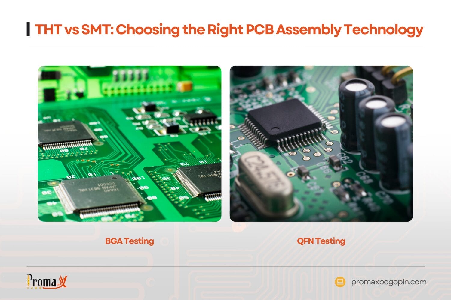
SMT Component Packages
| Package Type | Description | Applications |
|---|---|---|
| BGA | Ball Grid Array | High pin count ICs |
| QFN | Quad Flat No-leads | RF and power management |
| SOIC | Small Outline IC | General purpose ICs |
| 0805/0603 | Chip components | Resistors and capacitors |
SMT Assembly Process
- Solder paste printing through metal stencils
- Component placement using pick-and-place machines
- Reflow soldering with controlled temperature profiles
- Quality inspection per IPC J-STD-001 standards
How do Assembly Processes Differ?
THT requires hole drilling, component insertion, and wave soldering at 241°C to 260°C. SMT uses solder paste printing, automated placement, and reflow soldering with peak temperatures of 260°C for lead-free solder. The difference between SMT and THT is through-board versus surface mounting.
Wave Soldering vs. Reflow Soldering
Wave soldering moves the PCB over molten solder waves. Components get soldered one side at a time. Reflow soldering heats the entire assembly simultaneously. All SMT components connect at once.
Pin-in-Paste Technology
This hybrid technique fills THT holes with solder paste before component insertion. Both THT assemblies and SMT assemblies then reflow together. This eliminates separate wave soldering steps.
What are the Key Technical Differences?
| Specification | THT | SMT |
|---|---|---|
| Hole Requirements | Drilled and plated holes | No holes needed, some vias required for internal interconnects |
| Component Density | 10-20 per square inch | 50-100 per square inch |
| Solder Joint Type | Fillet joints | Heel and toe joints |
| Assembly Speed | 100–500 components/hour | 10,000+ components/hour |
| Rework Difficulty | Standard soldering iron | Hot air rework station |
Parasitic Effects
THT longer leads create higher parasitic inductance and capacitance. This limits high-frequency performance above 100MHz. SMD shorter connections reduce parasitics by 10x or more.
Mechanical Properties
THT joints withstand 50G shock loads. SMT joints typically handle 20G maximum. Thermal cycling performance varies by package type and PCB design.
Which Technology Offers Better Reliability?
SMT joints show lower thermal stress due to shorter leads and better thermal matching. THT joints provide superior mechanical strength under shock and vibration. Environmental conditions determine which performs better compared to SMT alternatives.
IPC Reliability Standards
Both technologies follow IPC-A-610 acceptability criteria. Class 1 covers general electronics. Class 2 handles dedicated service equipment. Class 3 applies to high-reliability applications.
Failure Analysis
THT failures occur at lead-to-pad interfaces during thermal cycling. SMT failures happen at component terminations or solder joint necking. Proper design prevents both failure modes in circuit board applications.
How do Costs Compare?
SMT costs less due to automated assembly and smaller PCB sizes. Material costs favor SMT through eliminated drilling operations. Labor costs drop significantly with automated pick-and-place equipment for prototype and production runs.
Equipment Investment
| Equipment Type | THT Cost | SMT Cost |
|---|---|---|
| Component insertion | $50K-200K | $200K-800K |
| Soldering system | $30K-100K | $100K-300K |
| Inspection equipment | $20K-80K | $50K-200K |
Higher SMT equipment costs pay back through increased throughput and lower per-unit assembly costs.
When Should You Choose THT?
Choose THT for mechanical connectors, power components, and high-vibration environments. THT works best for low volumes under 1000 units. Manual assembly capability makes THT ideal for field-serviceable equipment.
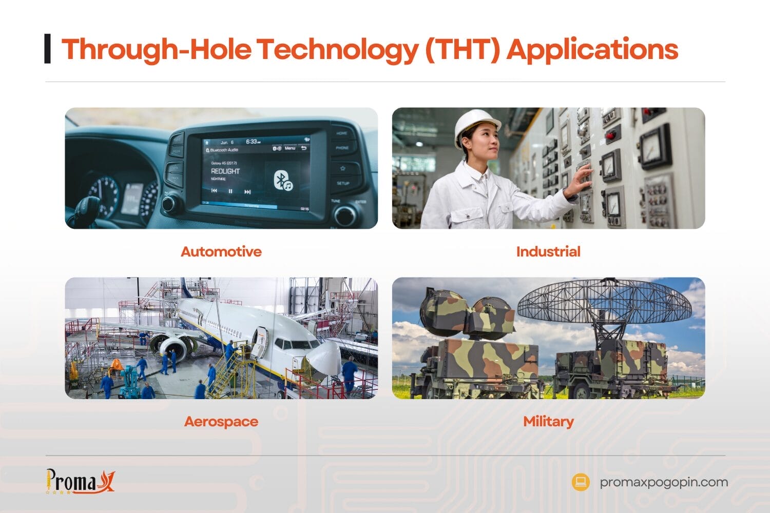
THT Applications
- Automotive — Engine control modules, power supplies
- Industrial — Motor drives, control panels
- Aerospace — Avionics, power distribution
- Military — Ruggedized communications equipment
High-Power Requirements
Components above 5W typically require THT mounting for thermal dissipation. Large heat sinks attach more securely to through-hole mounting systems.
When Should You Choose SMT?
Choose SMT for space-constrained designs requiring high component density. Automated production favors SMT above 1000 unit volumes. High-frequency circuits need SMT’s reduced parasitic effects on the side of the board.
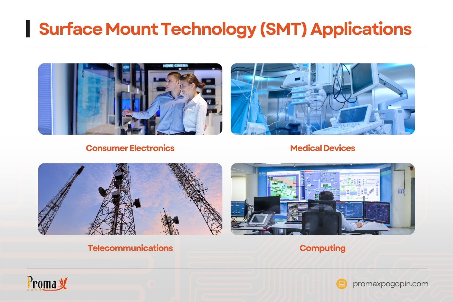
SMT Applications
- Consumer electronics — Smartphones, tablets, wearables
- Medical devices — Implantables, diagnostic equipment
- Telecommunications — Network equipment, base stations
- Computing — Processors, memory modules
Design for Manufacturability (DfM)
SMT designs require 0.1 mm minimum trace spacing and 0.2 mm via sizes. Component keep-out zones prevent placement conflicts. Thermal vias manage heat dissipation in high-power designs.
Can You Use Both Technologies Together?
Mixed-technology PCBs combine THT and SMT on the same board. Pin-in-paste soldering enables simultaneous reflow of both component types. This optimizes each technology’s strengths for PCB assembly projects.
Hybrid Design Guidelines
- Component height matching prevents reflow shadows
- Thermal profiling accommodates both package types
- Stencil design handles paste and holes simultaneously
- Assembly sequence may require selective processes
High-Density Interconnect (HDI) Boards
HDI designs use microvias and buried vias for maximum density. SMT components mount on multiple layers. THT components provide mechanical anchoring.
Technical Selection Criteria
Evaluate environmental conditions, production volume, and component availability. Create decision matrices weighing mechanical stress, space constraints, and cost factors. Consider long-term serviceability requirements for your printed circuit board design.
Environmental Analysis
Temperature cycling, vibration levels, and humidity exposure guide technology selection. Military specifications often require THT for critical connections. Consumer products favor SMT for cost and size.
Volume Thresholds
- Below 100 units: THT for simplicity
- 100–1000 units: Either technology viable
- Above 1000 units: SMT for cost efficiency
- Above 10,000 units: SMT strongly preferred
Get Professional PCB Assembly Solutions
Choosing the right PCB technology requires careful analysis of your specific needs. THT delivers unmatched mechanical strength for demanding applications. SMT provides superior density and cost efficiency for high-volume production. Many designs benefit from hybrid approaches combining both technologies.
Professional interconnect solutions ensure reliable connections regardless of your chosen assembly method. Contact our engineering team to discuss how precision connector systems can optimize your next PCB design project.
THT vs SMT FAQs
What solder temperature profiles work best for mixed THT/SMT assemblies?
Peak reflow temperatures of 245-260°C work for most mixed assemblies using lead-free solder. THT components must withstand SMT reflow temperatures, requiring careful component selection. Temperature profiling prevents thermal damage to sensitive components.
How do you prevent solder joint cracking in high-vibration applications?
Conformal coating protects solder joints from moisture and mechanical stress. Underfill materials reinforce BGA and flip-chip connections. Proper PCB support and mounting reduces board flexing during vibration.
What are the main design rules for successful pin-in-paste implementation?
Hole sizes should be 0.05-0.1 mm larger than component leads for proper paste filling. Stencil thickness of 0.1-0.15 mm provides adequate paste volume. Component standoff heights must accommodate paste thickness and prevent tombstoning.
Back to Top: THT vs SMT | Which PCB Assembly Technology Is Right for Your Project?